
"Benchwork" Details Series: Chapter 2: Stock Selection and Size Decisions

Our do-nothing assembly
In this post, I’m going to focus on the mundane…..choosing material, specifying cut sizes, and laying out the basics of your design for our “Do-Nothing” assembly. We’ll run through a few of the details of the assembly and “what if” your choices based on function and cost. As I said in my Tool Steel Selection post, many companies have moved away from this being your responsibility, however I think it’s still good to know because your stock choice and cut lengths signal your intention for how you want the part processed and that means time and cost.
But before we get started, a note on the difference between “proper” engineering practices and practical application because they are sometimes different and that difference can create the appearance of cluelessness if you don’t know some of this stuff. There is a story that is indelibly seared into my brain from when I was a 23 year old project engineer who was responsible for preparing the material orders for the details that were designed on my projects. For this one project, we needed custom washers in the design. They were like one inch diameter, had a half inch hole in them, and were maybe 3/8 thick. Ten were required. The designer’s stock callout was cold rolled steel, 1” diameter, 1/2” long, quantity of 10. This is actually the absolute correct callout from an engineering standpoint. Accepted design practice is to choose a stock size for a quantity of one and then specify the total quantity. But the toolroom supervisor strode into my office, threw this bag of steel disks that I had ordered for him onto my desk and said with considerable gusto “what the %&$! am I supposed to do with this?!?!?!?” I learned that day that when doing lathe details, you order a length that has extra material to chuck in the lathe and all parts can be machined and cut off from the stock that’s hanging out of the chuck. The right order was one piece that was around 6” long, not a bag of ten discs that he couldn’t process. This is also a big deal when calling out flat ground stock (FGS) or drill rod when the material only comes in 18” and 36” lengths. If you have a 1”x2”x2” piece and call out FGS with a quantity of 5 (the right engineering callout on your drawing), you may end up with five pieces 18 inches long (an $1100 error that I, ummm, may or may not have committed at some point) rather than one 18” piece that you can take all five pieces out of with material to spare. As I said, as a designer, this is technically not your problem…..the accepted practice for you is to call out the material for one piece and make sure the quantity is right. But, if you are responsible for ordering material or if you catch one of these situations and go out and talk to the person that is responsible for ordering the material, it will not only prevent a mistake, but it also shows you pay attention to how things actually get done beyond the design process.
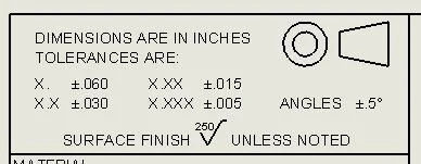
Print Tolerance Block Example
We’re about to take a look at some of the details in our do-nothing assembly, but first, a little info on tolerances implied by precision. I was always told that a two place decimal (xx.xx) carried a +/-.02” [.5mm] tolerance, a three place decimal (xx.xxx) carried a +/-.005” [.13mm] tolerance, and a four place decimal (xx.xxxx) carried a +/-.0005” [.012mm] tolerance and in the absence of an actual spec, that probably works well enough for your thought process. However, most customer drawing title corners (and your own company title corner) likely spell out their definition of tolerance, so look for that just in case it’s different from what I mentioned (as is the case of the example shown here).
Critical Details - A Ton of Decisions That May Make Your Head Spin

Main Detail Info
There will be certain details in your design that have a disproportionate effect on function, cost, and head scratching time trying to make sure you’ve accounted for everything versus the remaining details that you can kind of react to in the moment. The trick as a designer is to identify which details from your sketching or your vision of the station that fall into that category and then think through the full range of function, tolerances, and even stock selection that those details require prior to modeling, because once you have a bunch of things modeled and mated, the ah-ha moment of “wow, if I would have only designed that .100” narrower, I could have saved a ton of money!” requires a lot more effort to correct. In the case of our do-nothing assembly, that’s going to be the main detail that everything mounts to and has a variety of holes and pockets. So where to start….I’m not even sure there’s a first step 1, then step 2, then step 3 kind of sequence to go through. You have to simultaneously envision both the final function and the material choices available and work towards the middle from there. In this case, I know (ok, I’m making it up since it really doesn’t have a purpose, but stay with me) that the main detail will not be heat treated because it is basically serving as the mounting platform, so I can narrow my choices pretty quickly to 1018 cold rolled or A36 hot rolled bar stock (see the post on non-tool steel for my logic on those choices). Because several details are going to mount to it, I’m thinking some decent precision is warranted, so I will want to machine all the functional surfaces, which means HRS is a better choice because CRS can warp more when surfaces are machined. Now to the stock size. For some reason, we as humans love even numbers, and in this case, the detail is nominally 2” thick, but if I make it out of HRS, the stock will be undersized to start with, requiring a jump up to 2.25 stock thickness and the need to machine an excessive amount off of it just so I can feel good about saying 2.000 for the final thickness. So, one of the biggest takeaways from this post is to fight the urge to make everything nominal because 99% of the time, you can adjust the height by the combination of details to make the design work. In this case, you will see I intentionally chose a 1.900 final dimension for this detail so that 2” stock can be chosen and I’m only machining off less than .050 per side (likely with the big wet grinder that I talked about in Chapter 1). Now let’s talk about the 7” direction. In this case, I put a very tight parallelism tolerance on the two sides because in my made up scenario, I want to ensure the block can be fixtured very precisely for the machining of those bushing holes, but you’ll notice that I left the actual width at a two place decimal. You may not run into this scenario often, and even this example isn’t perfect, but that combination tells the machinist that the actual width is non-critical and he or she can use the entire tolerance band to achieve the parallelism. Now, I did take a risk in going with 7.00 final dimension because HRS typically runs .005” [.13mm] undersize and the implied tolerance on two place decimal is +/-.02” [.5mm], so I’ve really only left the machinist .015” total cleanup to meet the parallelism tolerance. Because bar stock is usually very consistent, I am gambling that’s enough, but it is a risk. That’s the kind of thing that you need to think through and maybe put a bigger one sided tolerance on that finished 7.00 dimension or finish it at 6.95 if you’re really worried. Finally, the 14” direction. you’ll notice that in the final print, I have it dimensioned with a two place decimal, telling the machinist that it’s not a critical dimension. But you will also notice that in the stock size, I have specified 14.13.” This combination tells the machinist that I would like the ends milled instead of saw cut. That is typical for higher dollar, more complex, and especially thicker details. We will chat more about saw cut ends a little later down in the post.

A2 Heat Treated Nest Example
Heat Treated Nest Detail Example
This one is pretty straightforward. Just like above, you want to imply that the ends of the part should be machined, so even though your final dimension is two place, you add an extra 1/8” (which is widely accepted for cutoff additions) to the 3” side in your stock callout. The two place dimension in the 2.75” direction that also matches the stock callout dimension implies stock size is ok, however, because we are pretending this is a heat treated nest, most likely made of A2 bar stock, there will be scale on the material that the toolmaker will clean up, but that’s just understood and a notation is typically not required. The only reason to even talk about this detail is the thickness dimension. In most nests (most being the imperative word), you will have some kind of functional adjustment in overall assembly in the vertical direction (a slide stop, a shim, etc), so it could be argued that a two place decimal would be accurate enough, and that would be true from a thickness perspective. But as a nest, you will want a level of parallelism between the mounting surface and the part holding surface that a two place callout is not sufficient for on its own. So you can either leave it two place and put in parallelism callouts on the drawing, or just simply make it a three place decimal. Why one over the other? Three place tolerances are not that hard to achieve on a mill and in this case, it’s just simpler and you’ll get consistency (nest to nest in a multiple nest design, or future replacement if a nest wears out) in both thickness and parallelism, so I’d argue it’s the better way to go. Plus, if you remember from the tool steel post, A2 bar stock is typically .02” [.5mm] oversized, so half inch stock is sufficient for a .500” final dimension. But either way will likely achieve what you want.
Simple Brackets

Brackets
There is only one thing to discuss on this very basic bracket (for some kind of switch or light or whatever we want it to be), and that’s the length callout. In the above examples, we made the stock length 1/8” longer than the final length dimension even though the final length wasn’t critical just to imply we wanted the ends cleaned up. You should check with your company policy, but even though it seems simple to clean up the ends of something, it does take maybe ten minutes or so and many companies believe you shouldn’t spend extra time/money on aesthetics only. For simple brackets, saving that ten minutes makes perfect sense and you convey that to the toolmaker by making the stock length callout the same as the final dimension on the print. This tells the toolmaker that a saw cut is fine. Full disclosure, some toolmakers think leaving anything sawcut is a negative reflection on their attention to detail and their craft and they may cut it off longer and clean up the ends anyway, but at least you’ve indicated it has no functional benefit to do so. And again, different companies push this practice harder than others. Your company may even want the above details sawcut. I tend towards a more middle of the road position. To me, any bracket, weldment, some simple plates, even some thinner heat treated pieces can be sawcut (when it doesn’t affect function) and it is virtually unnoticeable and does save you money. On expensive, heavily machined, thicker details, I do think the sawcut end sends a negative message to the customer about quality and I would advocate machining. It’s a balance and I will argue many times in future posts that adding costs for aesthetics isn’t beneficial to anyone, but some things do get noticed by influencers at the customer so it’s best for you to be on the same page as your management as to what image/pricepoint tradeoff you want to portray with your design practices.
Flipping Your Stock Dimensions

Flipped Dimensions
I wanted to include this in the post, although my example is pretty weak. I think we are relatively conditioned to list out material as thickness as the smallest dimension, width as the next larger dimension, and length as the longest dimension, but it can often be more beneficial to think of it functionally. If this little piece was maybe a switch dog or a catch to flip a spring loaded tool passing over it or something, you could keep it cheaper by leaving the ends saw cut just like the bracket above. Your mind may go to specifying the material as 0.5 x 1 x 1.5 as mentioned, but in this case (again, a fairly poor example, but there are instances where the reasoning is much more sound), I believe machinists tend to like to take cuts with their X axis more than Y and they will likely have the back vice jaw “zeroed” with their readout, so it could be more beneficial to call out the material as 0.5 x 1.5 x 1 so that you get stock finish on their preferred vice clamping points and the sawcut ends just hang in space. The takeaway is always be thinking about fixturing during manufacturing and final function and pick your stock to be the most beneficial overall.
I don’t see any other big standouts in the remaining details to talk about when it comes to stock selection and cut length callouts. Because the material choice has both a surface finish and dimensional impact, the best thing you can do to help you get faster at making the right decisions is to keep reviewing the tool steel and low carbon steel posts and researching materials online so that part of it just becomes second nature. And it may take the occasional toolroom guy throwing wasted stock on your desk and swearing at you to really create a teachable moment.